Heat Transfer simulation tasks
Heat transfer enhancement for heat exchanger elements
| Heat transfer enhancement for heat exchanger elements | 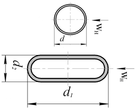 |
|
| Experiment at Re=15 000 | 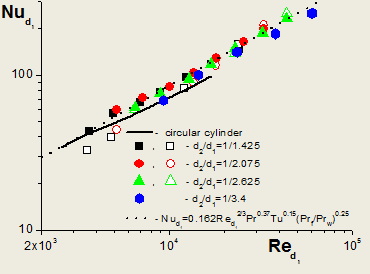
|
|
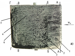 |
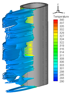 |
|
| Comparison of oval-shaped cylinders with circular ones | Modeling | |
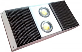
| Heat transfer enhancement for LED | ||
|
|
|
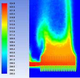 |
Source Power = 90 Wt Ambient T = 295 K Heat pipe thermal cond. =25000 Wt/mK |
Temperature distribution at the heat removal system surface |
| Heat wake above LED heat removal system | 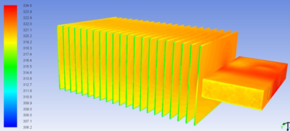 |
|
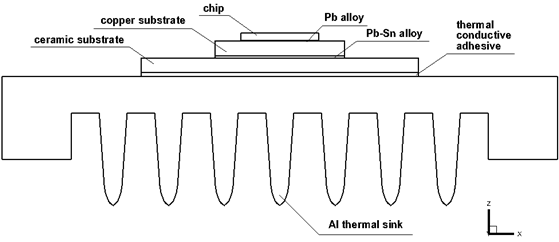
| Thermal regime of control system microelement of car generator |
|
|
|
|
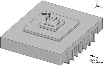
Surface of: chip – 5x5 mm, copper substrate – 8x8 mm, ceramic substrate – 15x15 mm, Al thermal sink – 25x30 mm |
Boundary conditions: Heat power of the chip – 3 Wt, Inlet air velocity – 5 m/s, Inlet air temperature – 398 K, Inlet turbulence level – 10% Used software: Ansys Fluent 14.5 |
Thermal regime of control system microelement of car generator
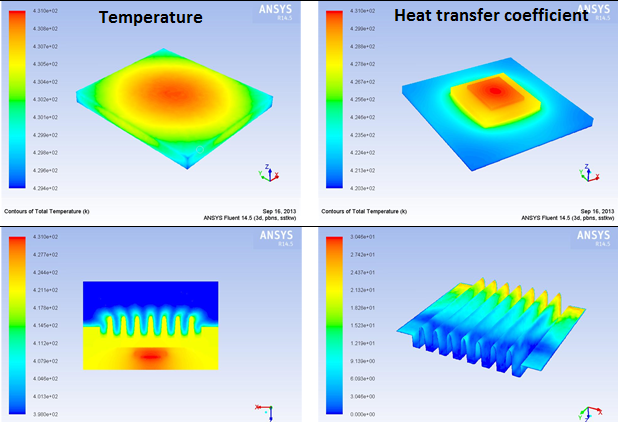
Q.: Which of the variants gives a minimal chip temperature?
| Nos | Properties | Averaged temperature of the chip surface | Maximal temperature of the chip |
|---|---|---|---|
| 1 | Copper – 7x7 mm, copper λ=150 Wt/(m K), adhesive λ=0.88 Wt/(m K) | 430.44 K (157.44 C) | 430.93 К (157.93 C) |
| 2 | Copper – 7x7 mm, change in ceramics Al2O3 to Al of grade AD0 with ρ=2710 kg/m3, λ=202.4 Wt/(m K), сp=930 J/(kg K); copper λ=380 Wt/(m K), adhesive λ=1.68 Wt/(m K) | 421.74 К (148.74 С) | 421.97 К (148.97 С) |
| 3 | Copper – 8x8 mm, copper λ=380 Wt/(m K), adhesive λ=0.88 Wt/(m K) | 423.59 K (150.59 C) | 423.87 K (150.87 C) |
| 4 | Copper – 8x8 mm, copper λ=380 Wt/(m K), adhesive λ=1.68 Wt/(m K) | 421.66 K (148.66 C) | 421.93 K (148.93 C) |
|
Variant 1: Copper – 7x7 mm, copper λ=150 Wt/(m K), adhesive λ=0.88 Wt/(m K) |
|
|
Variant 2: Copper – 7x7 mm, change in ceramics Al2O3 to Al with grade AD0 (ρ=2710 kg/m3, λ=202.4 Wt/(m K), сp=930 J/(kg K)); copper λ=380 Wt/(m K), adhesive λ=1.68 Wt/(m K) |

|
 |
|
|
 |
 |
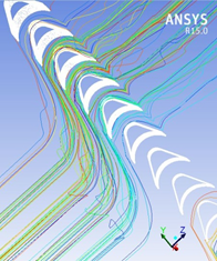 |
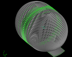
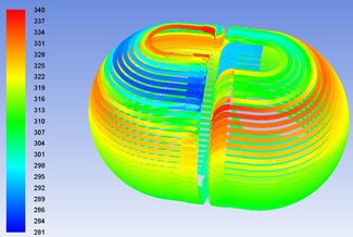
| CAD-model ‘Turbosphere’ | Temperature distribution in the gas pipeline | Streamlines near blades |


